 |
|
|
Washington, NC Real Estate - A cool site with real estate information in Washington, Bath, and Belhaven, North Carolina. Greenville, NC Real Estate - Another real estate site with information for Greenville and Winterville, NC. Morehead City, NC Real Estate - Another real estate site with information for Atlantic Beach and Emerald Isle, NC. Jacksonville, NC Real Estate - A real estate site with information for Jacksonville, NC and Richlands, NC and homes for sale. |
RS485 NetworkAll of the microcontroller nodes on my network communicate over EIA/RS485. I modeled my communication protocol after Ed Cheung's method since it seemed like a logical way to do it to me. Messages are in the form: RS_mmmm[ret], where:
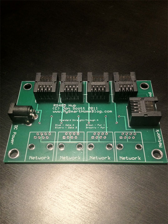
For more detailed information on how the nodes communicate, refer to Ed's (very informative) website. I use standard twisted pair Cat5 cable for my network medium since it is cheap and easily available. One pair is used for the RS485 communication and another is used to distribute 12 volts for nodes that get power from the network. The other two pairs are currently unused. I supply a maximum of 500mA (0.5 amps) of current for each “branch” of my network. Each node that uses the network-supplied power has a 5v voltage regulator (usually a 78M05CT) that steps the unregulated 12 volts down to a constant 5 volts for the microcontroller and peripherals to use. The RS485 network connects to the main controller using a bi-directional RS485 to DB9 serial adapter. RS485 Network HubI decided to design my own RS485 hubs so that I can place RJ45 connectors on the end of my terminations in my wiring closet and plug them into centralized hubs that can be easily troubleshooted and look aesthetically pleasing. The hubs support 8 devices that can be networked together along with a “trunking” port that allows me to connect multiple hubs together. Each hub is considered a “branch” on my network and has it's own 2.1mm barrel connector for connecting a 12v 500mA DC power supply from a plug in adapter. When a hub is trunked to the next hub, the power from one hub is not transferred to the next, only the network connection. I have a diode built in that makes sure only tip-positive power supplies are plugged in as well.
|
© Jon Scott 2012 -- All Rights Reserved.